David Ong, PhotonBytes.com
Perth, Australia
For the October 22–24, 2026 Mars Society
International Convention in the University of Southern California
https://convention.marssociety.org
https://www.marssociety.org/?mc_cid=b88f5afc23&mc_eid=69fe04f71b
Mars remain major obstacles to long-term human settlement. This paper investigates a conceptual planetary engineering approach in which a volatile-rich comet is deliberately redirected to impact Mars in order to restore atmospheric pressure and create localized habitable environments.
Comets are proposed in preference to asteroids for two reasons. First, their highly elliptical orbits permit relatively small perturbations applied near aphelion to produce large changes in trajectory and substantial impact velocities. Second, their abundant ice content provides an intrinsic source of reaction mass, allowing nuclear-driven vaporization to generate thrust without requiring propellant to be transported from Earth.
Although the comet itself contributes additional volatiles, the principal objective is to liberate substantially larger volatile reservoirs already present on Mars.Upon impact, the comet would deliver planetary-scale energies measured in tens of teratons of TNT equivalent. The conversion of kinetic energy into heat and mechanical work could contribute to the release of water and carbon dioxide trapped within the Martian polar caps and subsurface reservoirs, increasing atmospheric density and initiating long-term climatic modification.
Particular emphasis is placed upon the release of carbon dioxide from the southern polar deposits, which may contribute more effectively to atmospheric pressure restoration than water alone.Selection of the impact site constitutes a critical aspect of the concept. Candidate locations would be chosen to maximize the liberation of volatile materials from both polar regions, especially the carbon dioxide-rich southern polar deposits, as well as from subsurface reservoirs not yet fully characterized.
Additional consideration may be given to regions exhibiting evidence of residual volcanic or geothermal activity, with the aim of stimulating the release of carbon dioxide and other greenhouse gases from magma chambers, volcanic cavities, or partially active mantle sources. The impact location may therefore be optimized to exploit multiple atmospheric reservoirs simultaneously, including polar deposits, buried volatile-rich layers, and remnant volcanic systems that may still retain trapped greenhouse gases.
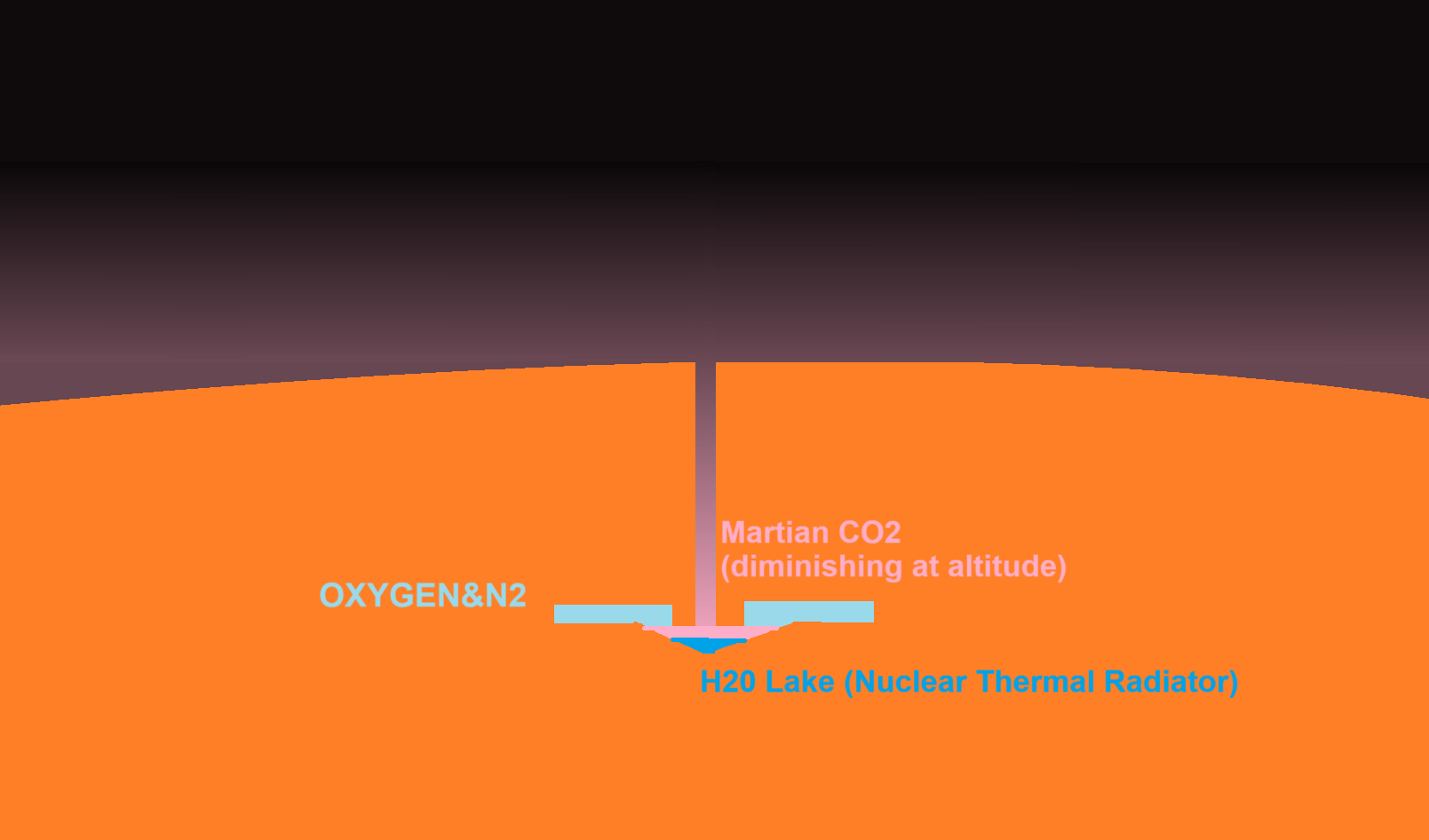
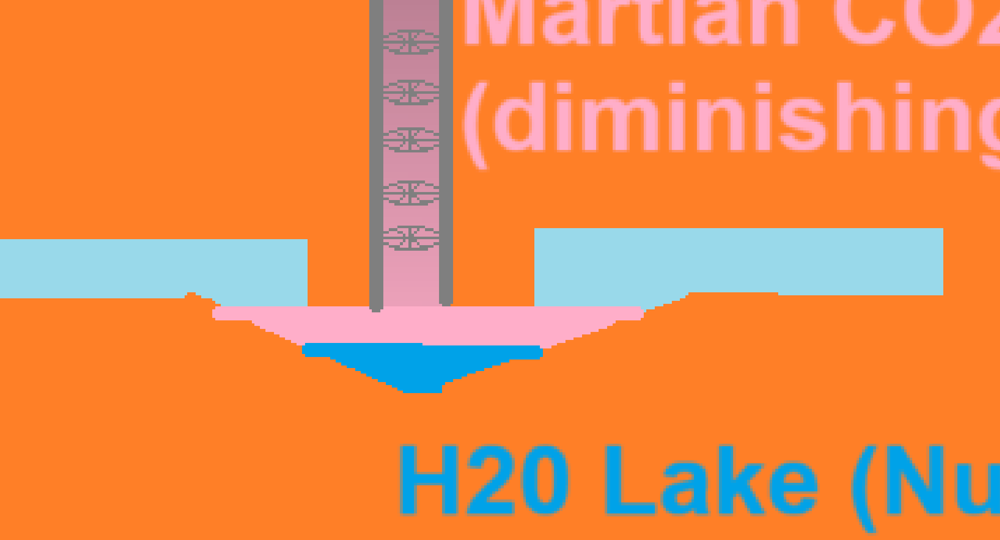
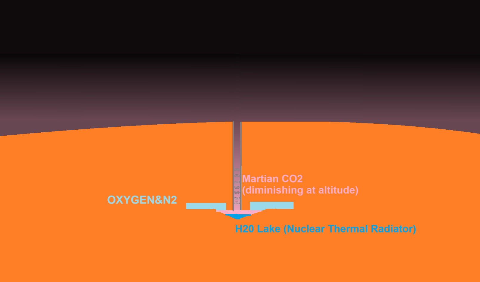
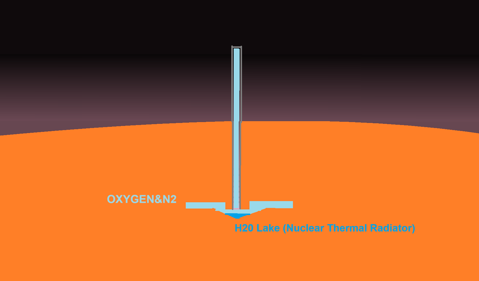
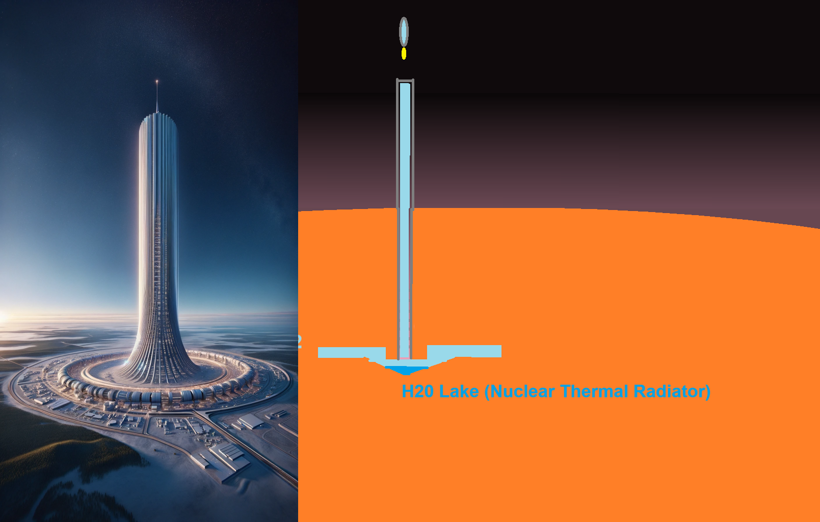
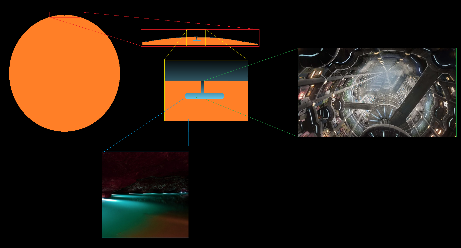
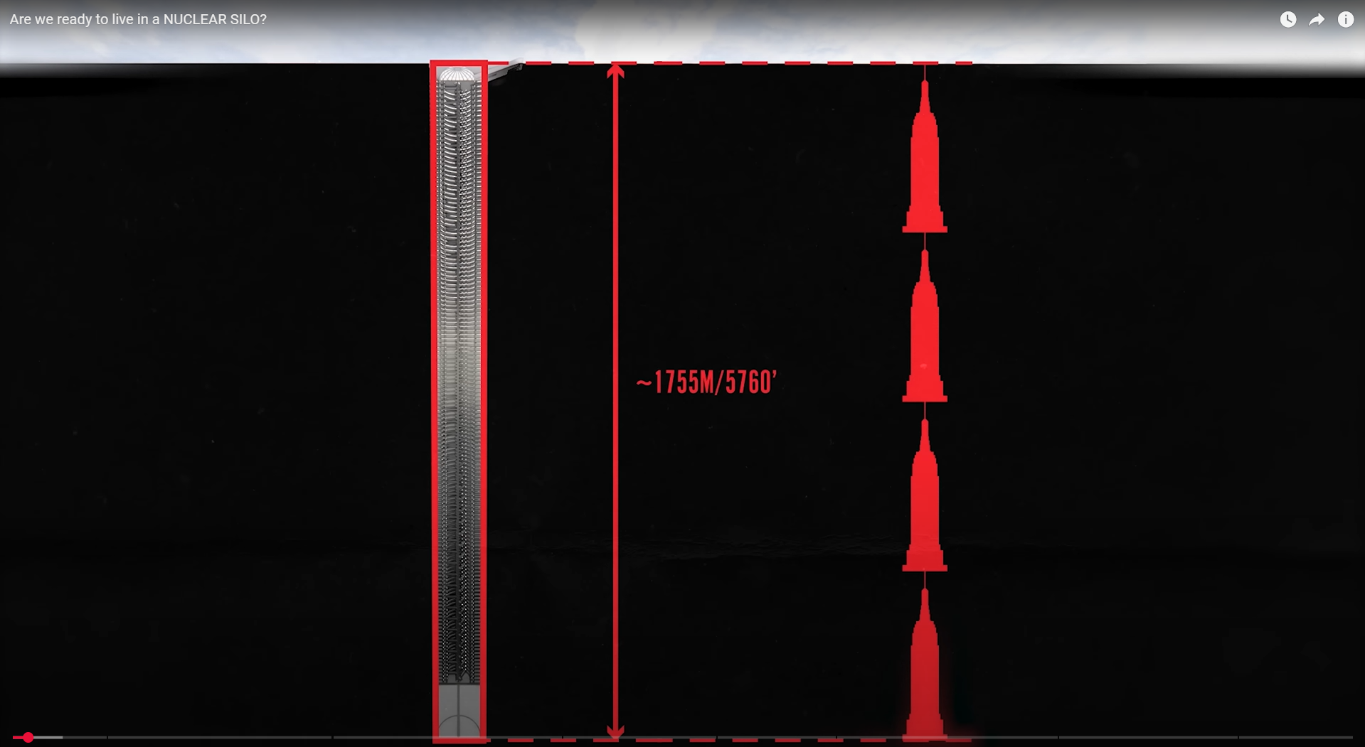
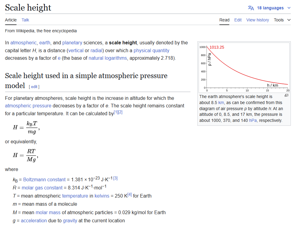
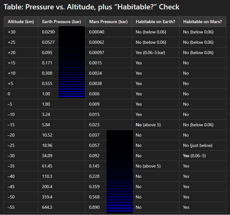
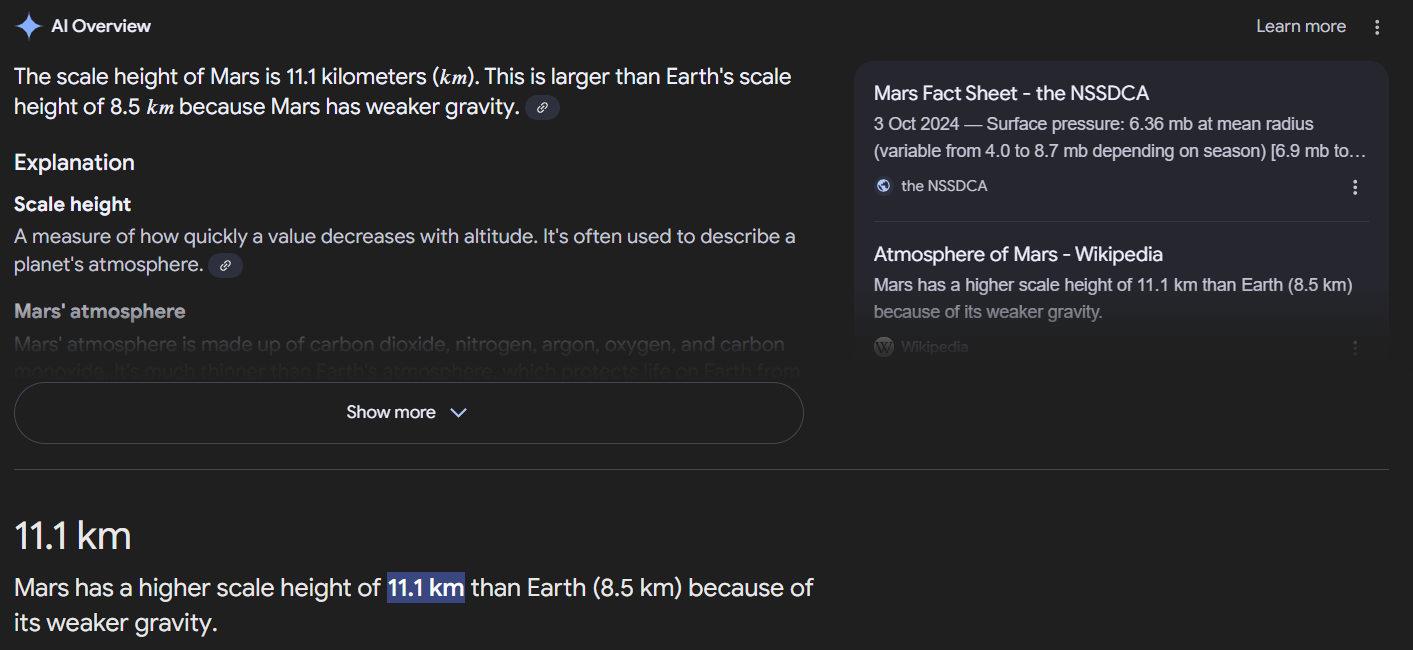
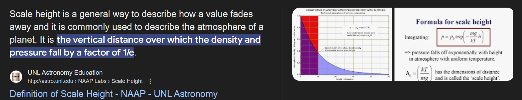
The impact angle represents an additional design parameter. Rather than merely maximizing energy deposition, the objective is to produce a crater geometry favorable to atmospheric retention. By taking advantage of the approximately 11-kilometer scale height of the Martian atmosphere, a sufficiently deep basin could potentially sustain significantly higher pressures near its floor than on the surrounding plains. Such a regional habitat could provide a favorable environment for future settlement and serve as a contingency strategy should global atmospheric restoration prove insufficient.
The proposed approach therefore incorporates a dual-purpose terraforming philosophy in which planetary-scale atmospheric enhancement constitutes the primary objective, while the creation of a naturally pressurized regional basin provides a secondary and potentially more achievable pathway toward sustained human habitation.Numerical simulations of crater formation and resulting topography would constitute an important component of the investigation.
Software such as the iSALE impact simulation code may be employed to model crater depth, geometry, ejecta distribution, and the atmospheric characteristics achievable within the resulting basin. These studies would aid in determining the optimal impact angle and location required to maximize both global atmospheric enhancement and local habitability.
This paper will discuss the orbital mechanics of comet redirection, propulsion utilizing indigenous cometary volatiles, impact energetics, strategic impact-site selection, stimulation of residual volcanic activity, crater geometry optimization, atmospheric effects, numerical crater simulations, and the engineering challenges associated with directed cometary impacts as a pathway toward the future habitation of Mars.