Image of the Day

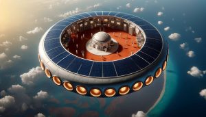
5 Gigawatt Solar powered Airship with anti missile laser defense. Phased Array Radar and optical array hybrid targeting system .

Shooting downward not only shortens the range to the target missile at apogee but reduces the energy requirements further more by having a shorer beam at higher altitude where air is less dense. This system should also works well against ballistic missiles falling from above in space for example from Iran. In which case the laser fires upward toward a vacuum environment where there is an even further reduced air density medium to convercome.

Electromagnet at Mar’s L1

This is a great paper that I am following up with Dr Bamford in regards to jump starting the L1 solenoid option discussed in it. The 10^7 joules required to be stored in the solenoid will first require a minimum power requirement to overcome the inductance. This could in theory be achieved by storing the required gigajoules in the form kinetic energy in a very high speed projectile travelling at km/s though the solenoid cavity to jump start it. The Kinetic energy should be slightly beyond the required theoretical power required to send a current through the solenoid. The magnetic projectile should also spin like a rifled bullet or like a flywheel so that it’s orientation is consistent as it passes through the central cavity of the solenoid while it interacts electro magnetically to jump start it with current and voltage.

https://www.researchgate.net/publication/355198821_How_to_create_an_artificial_magnetosphere_for_Mars

Above is a human scale flywheel that maintains orientation while spinning. Like a bullet. Bullets also spin to stay oriented consistently during it’s flight.

Speaking of flywheels it might also be possible to store the solar energy into the spin of a electromagnetic or magnetic flywheel connected to the solenoid’s closed circuit. However it’s disconnected until it ramps up enough energy by spinning up gradually with solar to to jump start the solenoid(with help possibly from the above mention spinning magnetic projectile idea) by reconnecting with it’s circuit once the required RPM is reached. If both ideas are used as a combination timing will be essential. Perhaps it’s more practical to pick one.

A third option and this is my favorite, use smaller solenoids called SMES(Super Conducting Energy Storage).

https://en.wikipedia.org/wiki/Superconducting_magnetic_energy_storage

These are basically solenoids designed to store energy like a battery rather than to sustain the largest magnetic field possible. They have lower inductance the smaller they are. We can have a small one start a larger one and that can start a larger one and this can go on until we start the main solenoid that protects Mars. Like a cascade tree array of SMES to jump start the megastructure solenoid.

In summary we have 3 options as a starting motor for the electromagnet of Mar’s L1, some of which can mix:

1. Flywheel Energy Storage Device.
2. High speed spinning magnet through the solenoid cavity at many km/s with sufficient Kinetic Energy.
3. Use SMES(Super Conducting Magnetic Energy Storage) cascade array.

Earth’s Magnetic Field Levitation

Chat GBT seems to think there are experiments that have successfully proved that grams of strong magnets have levitated without the assistacne of a second magnet instead floating directly on Earth’s Magnetic Field. But Google found no references of existing experiments all I found was the above video and the irrelevant though interesting reference below.

https://inventionstories.com/podcast/levitating-light-simon-morris-flyte/

The possibilities of variable blade Quadcopters

NASA’s Dragonfly mission uses Quadcopter technology but they are not variable blade. If each blade has an independent motor as well as ability to tilt blade angle independently this would enhance mission capabilities. Most quadcopters that are variable blade alter all 4 blades simultaneously and in an identical manner.  So far there are no commercial drones that have variable blade function for each motor and blade pair. This is a mistake because it’s omitting efficiencies that can be gain at various altitude and atmospheric pressures/densities for all kinds of aerodynamic flight maneuvers.

Man made Saucer

UPDATE:

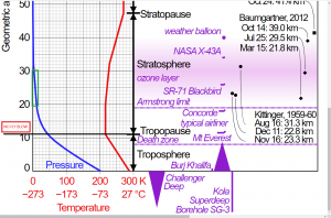
The High Altitude Platform Station also has applications for efficient access into orbit by reducing fuel mass requirements by 5-10%.

Below are some conceptual images of the station close to the surface of Antarctica to facilitate an expedition:


A modern ordinary shaped airship can still play a role in the future for faster more agile missions.

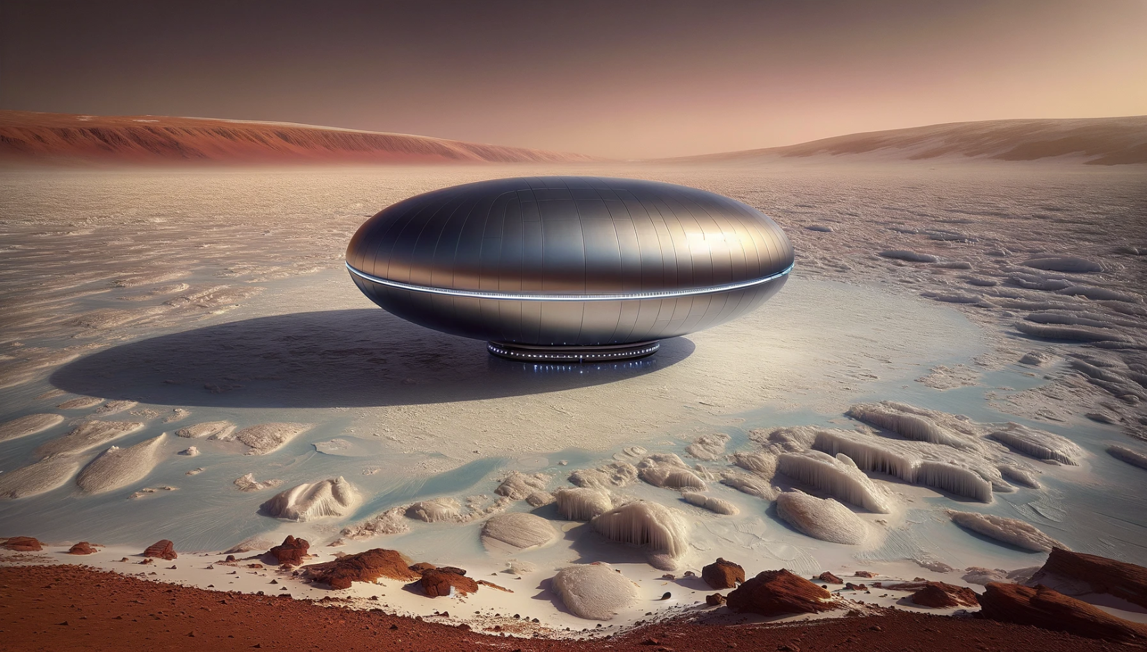
Saucer Shaped HAPs (High Altitude Platform Station

Update: Recently Hamas attacked Israel by overwhelming the Iron Dome System, here if the Iron Beam laser sister to Iron Dome was deployed on an airship such as the Russian variant mentioned below it would have enhanced the range and potency of the weapon while being out of range of Hamas’s anti air defenses.


Russian made 600 ton lifter.

Notice the cockpit is underneath and has 360 view facing downward with 45 deg angle windows much like the hindenburg did on the passenger cabin but unlike it , this uses helium. Not made to get as high as possible but with 600 ton of useful payload we imagine it can get to the stratosphere with reduced payload.


Uses:

  1. Above Cloud Telescope Array for Astronomy, with multiple ships the face of the Earth is the light collecting limit.
  2. Above Cloud Starshot/Light Sail Laser for interstellar light sail powered probes
  3. Ground/Air/Sea Tracking photometer for science and surveillance. For examples: Israeli ballistic missile defense as well as surveillance of Palestinian territories, Scientific expeditions to Antarctica and South America in the safety and comfort of a pressurised cabin.
  4. Floating Aircraft Carrier
  5. Floating Drone Carrier
  6. Floating Battleship with munitions and anti air defences normally used on Navy Marine vessels such as radar guided air cannons and laser defense systems.
  7. Orbital/sub-orbital launch platform to assist smaller rockets to reach space.
  8. Floating Hotel
  9. Floating Research Lab for low Air Pressure studies such as simulating Martian pressure altitudes.
  10. Anti Ballistic Missile Platform with a floating phased radar array.
  11. Microwave transmission of energy to the surface from solar.
  12. Communications relay to replace communications satellites in geostationary orbit.
AI analysis
ChatGPT:

Designing a rigid airship in the shape of a saucer or disc has several potential advantages, although it’s important to note that this concept hasn’t been widely pursued or proven in practice. Here are some theoretical advantages of such a design:

  1. Aerodynamic Efficiency: The saucer or disc shape could potentially offer better aerodynamic efficiency compared to traditional airship designs. The streamlined shape might reduce drag and turbulence, allowing for smoother and more efficient flight through the air.
  2. Stability: The disc shape could provide inherent stability due to its wide base and potentially lower center of gravity. This stability could make it easier to control and maneuver, especially in challenging weather conditions.
  3. Lift Efficiency: The saucer shape could distribute lift more evenly across the entire bottom surface, potentially leading to better lift efficiency. This could result in improved payload capacity and longer flight endurance.
  4. Omni-Directional Maneuverability: A saucer-shaped airship might have the ability to rotate and maneuver in any direction more easily than traditional airships. This could be advantageous for tasks that require precise positioning or sudden changes in direction.
  5. Visibility: The flat, circular design could provide better visibility from the central control or observation area, which could be situated on the upper surface of the saucer.
  6. Novelty and Attention: A saucer-shaped airship would undoubtedly attract attention due to its unique design, which could be advantageous for promotional purposes, advertising, or special events.
  7. Potential Stealth: Depending on the construction materials and design features, a saucer-shaped airship might have reduced radar cross-section and acoustic signature, potentially offering some degree of stealthiness.

However, it’s important to consider the challenges and practical limitations associated with designing and operating such a craft:

  1. Structural Challenges: Creating a rigid airship in the shape of a saucer would present significant engineering challenges. The structure would need to withstand both internal and external forces, including the pressure differential between the inside and outside of the craft.
  2. Balancing and Stability: Achieving proper balance and stability in a saucer-shaped airship could be complex, as the weight distribution would need to be carefully managed to prevent tipping or instability.
  3. Propulsion and Control: Developing effective propulsion and control systems for a saucer-shaped airship would require innovative solutions, as traditional methods might not apply as well to this shape.
  4. Landing and Mooring: Landing and mooring a saucer-shaped airship could be more challenging than with conventional airship designs due to the unique shape and potential difficulty in maintaining stability during ground operations.
  5. Manufacturing and Cost: Constructing a saucer-shaped airship would likely involve specialized manufacturing processes, which could be expensive and technically demanding.

Overall, while a saucer-shaped rigid airship presents interesting theoretical advantages, the practical challenges and complexities of design, engineering, and operation would need to be thoroughly addressed for such a concept to become a viable reality. As of my last update in September 2021, there have been no widely known successful attempts to create operational saucer-shaped airships.

Historical Reference:

https://en.wikipedia.org/wiki/High-altitude_platform_station

Cube Shaped interstellar spacecraft – Dual Stage Ion Drives


Dual Stage Ion Drives – New Mars Forums Discussions:
https://newmars.com/forums/viewtopic.php?id=10491

UPDATE:

The following article makes a big case to building a hydrogen based ion drive:

https://space.stackexchange.com/questions/43389/have-light-gases-like-hydrogen-or-helium-been-explored-for-ion-propulsion


There are signs of technology suppression by global powers of the dual grid 2 stage ion drive technology that was being jointly developed between ESA and Australia. The lead scientist has mysteriously passed away over suspicious circumstances just when the team was making head way.

https://en.wikipedia.org/wiki/Dual-Stage_4-Grid

https://en.wikipedia.org/wiki/Small_modular_reactor

The numbers supplied by wikipedia:

Power: 250kW

Isp: 19,000s

Diameter: 2.5m

The theoretical scaled up numbers above if valid would mean significant capabilities for space travel in the future. I came up with a cubic shape configuration for an interstellar space craft to maximize the surface area of any ion drive exhaust either as a single gigantic engine or a grid array of smaller units. Solar would also be able to take advantage of the nature of the cube to maximize solar radiation intake to maximize solar power.

These numbers would mean that a space craft such as my design only 17m by 17m with conservative numbers for a gigawatt reactor would be able to get to Mars in weeks and Titan in months. The greatest challenge to this design would be to minimize the weight of a 2.5gigawatt reactor and make it be 5-10 tons. This is the greatest challenge. The surface sides of the cube will be able to house panels that can efficiently radiate the reactor waste heat.

Alternatively we can completely eliminate the reactor and just rely on solar which definitely will make this endeavor possible for Mars alone. Without the reactor the entire ship will be 5-10 tons lighter boosting it’s acceleration capabilities and bringing it’s entire mass down to 10 tons.